
Micro Coriolis Low Flow Meter Interface Guide: Outputs, Power, and Communication
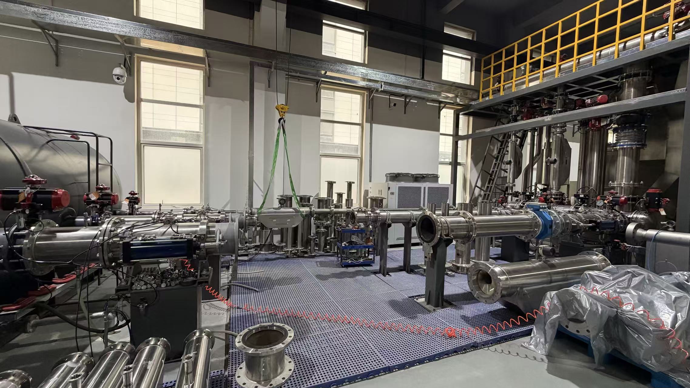
Specify a micro Coriolis low flow meter from the process boundary outward. First lock the fluid, flow range, pressure, temperature, wetted material, process connection, hazardous-area classification and the receiving control system. Then choose the electrical interface: 4-20 mA, pulse, frequency, MODBUS RTU, HART, Profibus-DP/PA, RS485/RS232, and 15 V DC or 24 V DC power. The interface must be an approved option for the exact meter and electronics; a protocol named in a family brochure is not enough for an order.
Silver Automation Instruments, founded in 2010, is a Nanjing-based instrument manufacturer whose supplied product records include the Micro Coriolis mass flow meter SH-CMF-FE. For this model, the supplied certification records provide useful starting points: ATEX Zone 2 record ICR/VC/HM251296, CE record 1N220422.SAIUW36 to EN IEC 61326-1:2021, and ISO 9001:2015 certificate 79625Q0002107R0S. Those records verify product-level conformity and quality-system scope; they do not replace the interface datasheet, nameplate, hazardous-area schedule or project acceptance test.
Problem definition: the interface is part of the measurement system
Interface mismatch usually appears after the mechanical selection is already fixed. A PLC card expects a 4-20 mA analog rate, but the meter order carries a pulse output. A DCS supports HART, but the loop resistance and barrier voltage drop have not been checked. A skid builder needs density and temperature as well as mass flow, but the chosen digital path does not expose those variables to the controller. A hazardous-area installer receives a Zone 2 certificate, then discovers that the cable entry, barrier or remote electronics detail is not covered by the planned installation.
These are not abstract integration issues. They affect wiring, PLC programming, hazardous-area assessment, acceptance testing and spare-part strategy. For a low flow meter, the small measurement span can make scaling and resolution more noticeable, so the electrical interface should be defined with the same care as the sensor size and process connection.
The practical rule is simple: define the receiver before the transmitter. List what the control system must receive, how often, at what resolution, and under which alarm or diagnostic condition. Then map that requirement to the approved meter option. Do not choose a protocol because it appears modern or familiar; choose it because the receiving system can use it correctly and the meter can be supplied and certified with it.
Industry background: why compact Coriolis meters need clear interface planning
A 2026 Fortune Business Insights estimate places Coriolis flow meters at 26.77% of the intelligent flow meter market. Grand View Research expects the 2-inch and smaller pipe-size segment to see the fastest growth through 2030, with demand linked to pharmaceuticals and food and beverage. P&S Intelligence values the global microfluidic devices market at USD 22.1 billion in 2024, with a 12.2% compound annual growth rate. These figures describe the market context for compact and low-flow measurement; they do not establish which output, protocol or power option is correct for a specific installation.
For the buyer, the implication is practical. Small-line projects often combine a flow sensor with a skid controller, a data logger, a batch system or a laboratory information system. The meter is not only a mechanical device. It is a data source. That is why the interface schedule belongs in the request for quotation, not in a post-order email.
Specification sequence for a micro Coriolis installation
A reliable interface decision follows a fixed sequence. Changing the order can create rework because later choices depend on earlier process facts.
- Define the process boundary. Record the fluid, minimum and maximum flow, pressure, temperature, density or viscosity where relevant, allowable pressure drop, wetted-material requirement and process connection. Confirm whether the line is liquid, gas or a multiphase condition requiring project review.
- Define the data consumer. Identify the PLC, DCS, flow computer, batch controller, data logger or laboratory system. List the required variables: mass flow, volume flow, temperature, density, total, alarm status or diagnostics.
- Select the primary output. Use 4-20 mA for an analog rate signal, pulse for totalization or batching, frequency for a rate input, and a digital protocol when configuration, diagnostics or multiple variables are needed.
- Select the digital protocol and physical layer. Confirm MODBUS RTU over RS485, HART on a 4-20 mA loop, Profibus-DP/PA, or RS485/RS232 as applicable. Check the master device, register map, GSD or DD file, baud rate, parity, termination and grounding.
- Select power and loop architecture. Confirm 15 V DC or 24 V DC input, current consumption, polarity, isolation, loop compliance voltage and any barrier or isolator voltage drop.
- Verify hazardous-area scope. Match the exact electronics, enclosure, cable entry and associated apparatus to the ATEX certificate and installation instructions. Do not treat a product-level Zone 2 record as blanket approval for every accessory combination.
- Verify pressure, material and connection. Confirm the pressure rating at operating temperature, wetted-material compatibility, seal material and process connection. These are process-boundary decisions; they are not created by the communication protocol.
- Lock the order code and acceptance test. Record the interface, power, protocol, cable entry, documentation, calibration test and factory acceptance criteria in the purchase order.
Output and communication options: what each interface does
The same micro Coriolis meter family may be offered with different electrical options, but the availability of each option must be confirmed for the exact model and order code. The descriptions below explain the integration role of common interfaces; they are not a statement that every option is standard on SH-CMF-FE.
4-20 mA
4-20 mA is an analog current loop normally used to send a rate variable to a PLC or DCS. It is simple to wire and familiar to most control engineers. The buyer should confirm whether the output is active or passive, whether the meter is loop-powered or separately powered, the maximum loop load, the isolation arrangement and whether HART digital communication is superimposed on the same loop. In a hazardous area, the barrier or isolator resistance and voltage drop belong in the loop calculation.
Pulse output
A pulse output is normally used for totalization, dosing or batch control. Each pulse represents a defined quantity, so the receiving counter must match the pulse scaling, pulse width and maximum pulse frequency. The buyer should confirm whether the pulse is active or passive, its electrical isolation, reset behavior and the low-flow cutoff if one is configured. A pulse output that is correct for a slow totalizer may not suit a high-speed batch controller.
Frequency output
A frequency output represents flow rate as a frequency rather than a current. It can suit a controller with a frequency input or a dedicated flow computer. The specification should state the frequency range, output amplitude, scaling, load and low-flow behavior. The receiving device must be able to measure the frequency accurately across the required flow range, especially at the low end.
MODBUS RTU
MODBUS RTU is a digital protocol commonly carried over RS485. It can support multiple variables and diagnostics on a multidrop network. The integration checklist should include the slave address, baud rate, parity, stop bits, register map, data format, byte order, termination and shielding. The master must be able to poll the meter at the required rate without delaying higher-priority control tasks.
HART
HART adds digital communication to a 4-20 mA loop. It is often used for configuration, diagnostics and secondary variables while the analog current carries the primary rate. The buyer should confirm the HART revision, device description file, loop resistance and whether the barrier or isolator passes HART communication. HART is not a substitute for checking the analog loop budget.
Profibus-DP and Profibus-PA
Profibus-DP is a digital fieldbus used for discrete control and fast cyclic data exchange. Profibus-PA is used in process automation and can be relevant where a segment architecture and hazardous-area design are required. For either option, confirm the GSD file, baud rate or segment design, termination, master configuration and diagnostic mapping. Profibus-PA also requires the segment coupler, power and hazardous-area design to be reviewed as a system.
RS485 and RS232
RS485 is a differential serial physical layer that can support multidrop networks. RS232 is normally point-to-point. A meter may use either physical layer with a defined protocol, so the buyer should not assume that an RS485 terminal means MODBUS RTU unless the order code and register map confirm it. Check isolation, cable type, converter requirements, termination and grounding.
| Interface option | Typical integration role | Architecture to confirm | Specification checks before order |
|---|---|---|---|
| 4-20 mA | Analog rate signal to PLC or DCS | Two-wire loop or separately powered | Active or passive output, load, isolation, HART overlay, barrier voltage drop |
| Pulse | Totalization, dosing or batch counting | Pulse input on counter or PLC | Scaling, pulse width, maximum frequency, active or passive, reset |
| Frequency | Rate signal to frequency input | Frequency counter or flow computer | Frequency range, amplitude, scaling, load, low-flow cutoff |
| MODBUS RTU | Multi-variable digital communication | RS485 multidrop | Slave address, baud rate, parity, register map, termination, shielding |
| HART | Configuration and diagnostics on a 4-20 mA loop | Point-to-point analog loop | HART revision, DD file, loop resistance, barrier compatibility |
| Profibus-DP | Fieldbus control network | RS485 segment with master | GSD file, baud rate, termination, diagnostic mapping |
| Profibus-PA | Process automation and hazardous-area segment | MBP-IS segment with coupler | Segment design, coupler, power, GSD, hazardous-area assessment |
| RS485/RS232 | Serial communication and configuration | RS485 multidrop or RS232 point-to-point | Protocol identity, isolation, converter, cable, grounding |
Power: 15 V DC and 24 V DC are not interchangeable assumptions
Power selection is often treated as a minor line item, but it affects wiring, barrier selection, enclosure space and spare-part strategy. The topic includes 15 V DC and 24 V DC options. The exact input range, current consumption, polarity, isolation and minimum terminal voltage must be confirmed on the meter nameplate and approved datasheet. A 24 V DC supply should not be connected to a 15 V DC input without confirming that the input is rated for it, and a 15 V DC supply may not provide enough voltage after barrier and cable losses for a 24 V DC circuit.
For a 4-20 mA loop, the power architecture can be loop-powered or separately powered. The loop compliance voltage, total loop resistance and barrier voltage drop determine whether the meter can operate across the full current range. For digital protocols, confirm the supply current and the effect of segment couplers, repeaters or isolators. For pulse and frequency outputs, confirm the output circuit type and whether an external pull-up or load is required.
| Power or loop arrangement | What it affects | Checks before release to procurement |
|---|---|---|
| 15 V DC supply | Input compatibility, current draw and barrier voltage margin | Confirm rated input range, polarity and minimum terminal voltage at full load |
| 24 V DC supply | Common industrial supply compatibility and isolation | Confirm maximum input voltage, current consumption and protection requirements |
| Loop-powered 4-20 mA | Loop compliance, load and hazardous-area barrier drop | Calculate total loop resistance and confirm operation at the minimum supply voltage |
| Separately powered electronics | Power wiring, isolation and output common reference | Confirm supply and output isolation, grounding and signal reference |
ATEX: the certificate defines a scope, not a universal permission
The supplied ATEX certificate ICR/VC/HM251296 lists the Micro Coriolis mass flow meter SH-CMF-FE within a Zone 2 scope and references IEC 60079-0:2018+A11:2024, EN 60079-1:2014+A11:2024 and EN IEC 60079-31:2024. The certificate was issued on 2025-12-09 and expires on 2030-12-09. That is a product-level record. It does not by itself tell the buyer that every output, cable gland, barrier, display or remote transmitter combination has been assessed for the intended installation.
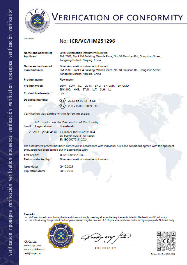
For execution, build a hazardous-area schedule around the exact order. Record the certificate number, marking, enclosure, cable entry, supply parameters, output circuit and any associated apparatus. If a digital protocol requires a segment coupler, repeater or isolator, include it in the assessment. The installation instructions and certificate conditions remain part of the approval; a protocol choice cannot override them.
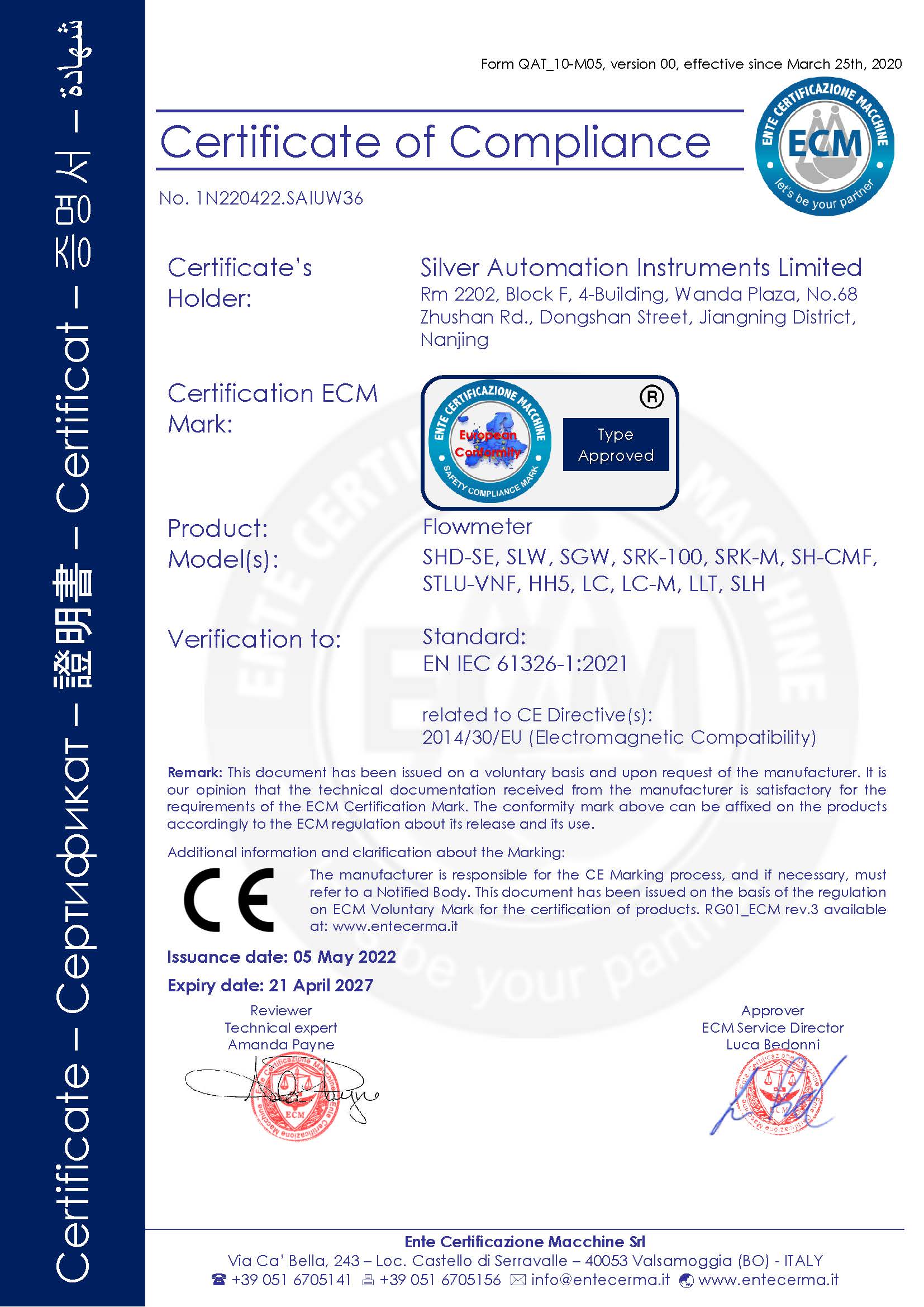
The CE record adds a separate conformity anchor. CE certificate 1N220422.SAIUW36 was issued by Ente Certificazione Macchine Srl on 2022-05-05, expires on 2027-04-21, and cites EN IEC 61326-1:2021 for flow meters. It also lists SH-CMF-FE in the supplied related-product records. The ISO 9001:2015 certificate 79625Q0002107R0S was issued on 2025-07-10 and expires on 2028-07-09. These records support the quality and conformity file; they do not replace the project EMC and installation review.
Pressure rating, material and process connection come before the protocol
The electrical interface does not set the pressure rating. Pressure containment belongs to the sensor body, wetted parts, seals and process connection at the operating temperature. A digital output can carry a pressure or temperature value, but it cannot make a low-pressure connection suitable for a high-pressure line. For a micro Coriolis project, confirm the pressure rating of the exact wetted sensor and connection, then select the electronics that meet the area and integration requirements.
Supplied case records show why this order matters. In Chile, one Coriolis mass flow meter was used to measure nitrogen gas at around 700 bar; the record states a high-pressure design capable of withstanding 700 bar or higher and stable measurement for more than three years. In Serbia, two Coriolis meters measured high-temperature, high-viscosity asphalt at approximately 250°C, with density and temperature displayed, for more than five years. These cases document specific Coriolis configurations. They do not establish that every micro Coriolis size, connection or electronics option is rated to 700 bar or 250°C.
Material selection follows the same rule. In Malaysia, one Coriolis meter used tantalum material for corrosive chlorine gas. In Singapore, four SRK-100 thermal mass flow meters used PTFE-coated insertion sensors for slightly corrosive biogas at around 10 mbar in a 4-inch pipeline. These are application-specific material choices, not a catalogue of wetted materials for SH-CMF-FE. The buyer should confirm the wetted material, seal and connection against the actual medium and cleaning regime.
Process connection selection affects pressure class, sealing, installation space and hazardous-area installation. Fix the connection type and size before the interface is released to production. If the line requires a hygienic connection, a flanged connection or another project-specific end, confirm that it is included in the approved model configuration. Do not let a communication preference delay the mechanical review.
| Verified anchor for SH-CMF-FE | Supplied record | What it means for the interface enquiry |
|---|---|---|
| ATEX Zone 2 | Certificate ICR/VC/HM251296, issued 2025-12-09, expires 2030-12-09 | Use the exact electronics and installation conditions within the certificate scope |
| CE / EMC | Certificate 1N220422.SAIUW36, EN IEC 61326-1:2021, expires 2027-04-21 | Include shielding, grounding and cable routing in the installation review |
| Quality system | ISO 9001:2015 certificate 79625Q0002107R0S, expires 2028-07-09 | Request calibration and acceptance records with the order |
| OEM/ODM capability | OEM/ODM production, logo customization, MOQ 1 unit, monthly capacity 2000 units | Confirm the interface, register map, connector and acceptance test for the OEM build |
| Interface and power options | Not specified in the supplied product facts for SH-CMF-FE | Confirm 4-20 mA, pulse, frequency, MODBUS RTU, HART, Profibus-DP/PA, RS485/RS232, 15 V DC or 24 V DC in the exact order code |
Step-by-step execution: from evaluation to purchase order
At the evaluation and execution stages, the interface should be converted into a controlled specification rather than a list of preferred features. The following workflow keeps the electrical, hazardous-area and process decisions aligned.
- Issue an interface schedule with the RFQ. State the required output, protocol, power, connector, cable entry, hazardous-area classification, receiver type and acceptance test. Attach the existing control-system wiring standard if one exists.
- Request the exact model datasheet and order code. Confirm that the proposed SH-CMF-FE configuration includes the requested interface and power option. Ask for the nameplate data, terminal diagram, certificate copy and installation instructions.
- Check the digital integration file. For MODBUS RTU, request the register map. For HART, request the DD file and revision. For Profibus-DP/PA, request the GSD file and diagnostic mapping. For RS485/RS232, confirm the protocol identity and serial settings.
- Review power and loop calculations. Confirm 15 V DC or 24 V DC input, current consumption, isolation, loop compliance and barrier voltage drop. Check the output load and whether an external pull-up or converter is required.
- Match the hazardous-area schedule. Compare the exact electronics, enclosure, cable entry and associated apparatus with ATEX certificate ICR/VC/HM251296 and the installation instructions. Record any project-specific conditions.
- Confirm pressure, material and connection. Verify the pressure rating at operating temperature, wetted material, seal and process connection. Do not release the order until the mechanical and electrical interfaces are consistent.
- Agree the acceptance test. Define pre-shipment calibration, visual inspection and an optional factory acceptance test. Include signal verification for the selected output, protocol and power arrangement.
Use cases: process conditions that shape the interface decision
The supplied cases below are documented Coriolis or thermal applications, not all SH-CMF-FE installations. They are useful because they show how process conditions create interface requirements that should be captured before the order.
| Documented application | Verified fact from supplied records | Interface or specification lesson |
|---|---|---|
| High-pressure nitrogen, Chile | One Coriolis mass flow meter at around 700 bar, stable measurement for more than 3 years | Pressure rating is a process-boundary check; the communication protocol does not create pressure capability |
| High-viscosity syrup, Thailand | Coriolis meter with accuracy up to 0.1%, displaying volume flow, sugar verticality and density, operating more than 5 years | If the controller needs multiple variables, confirm which are available on the selected digital or analog output |
| High-temperature asphalt, Serbia | Two Coriolis meters, approximately 250°C, density and temperature displayed, more than 5 years | Temperature affects the sensor and installation; confirm electronics location and output variables |
| Corrosive chlorine gas, Malaysia | One Coriolis meter with tantalum material for liquid chlorine corrosion gas | Wetted-material selection precedes the protocol decision |
| Cryogenic liquid oxygen, India | Three Coriolis meters at -183°C, accuracy within 0.2% to 0.5% as reported by customer feedback | Ultra-low temperature service requires project review beyond the electrical interface |
| Low-flow air leak detection, China | Three SRK-DL thermal mass flow meters detecting leaks as low as 2 sccm, operating more than 10 years | Low-flow gas capability can come from thermal technology; do not assume a Coriolis model or interface |
OEM, calibration and acceptance checks
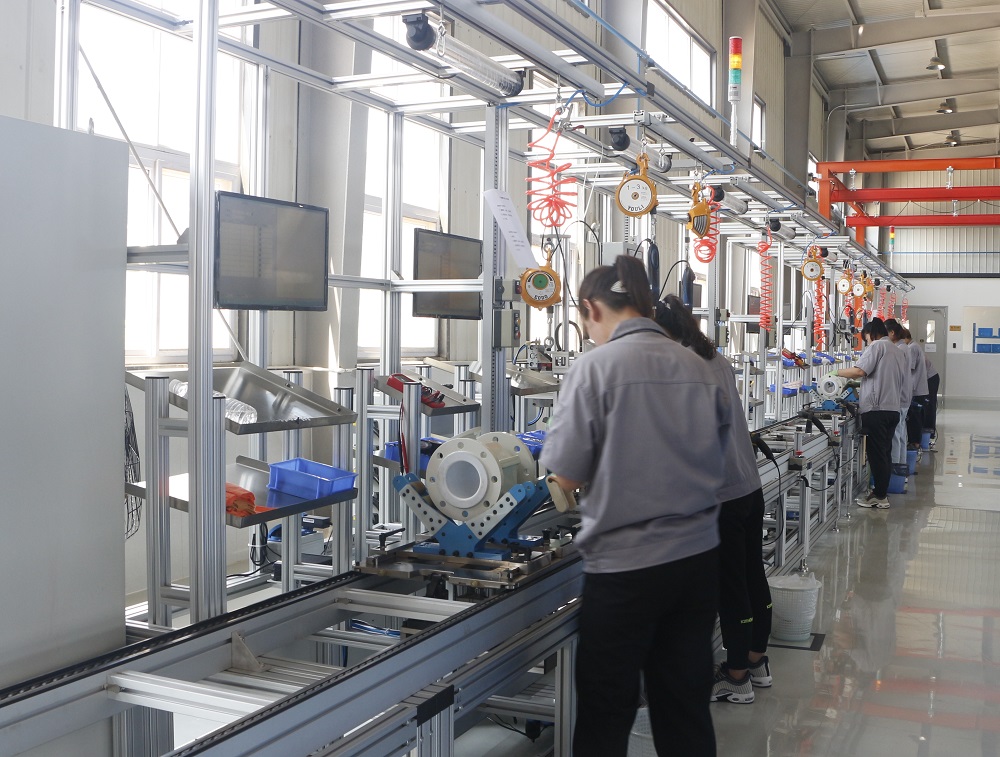
The supplied capability record for Silver Automation Instruments lists OEM/ODM production, logo customization, MOQ 1 unit, monthly capacity of 2000 units, lead time of 10-12 working days, calibration test and remote support. For a microfluidic OEM project, these commercial capabilities are only the starting point. The technical package should also define the interface, connector, enclosure, firmware or register map, power arrangement and acceptance criteria.
The supplied FAQ record states MOQ 1 unit, EXW, FOB or CIF delivery terms, pre-shipment calibration test, visual inspection, optional factory acceptance test and 100% T/T in advance. These are purchasing terms. They do not confirm that a particular protocol is available. The purchase order should separate commercial terms from the approved technical configuration.
A practical factory acceptance test for a low flow meter with digital or analog output should verify the agreed signal at defined points, check scaling and totalization, confirm communication with the specified master, inspect the power and wiring arrangement, and review the certificate and calibration records. If the meter will be installed in a hazardous area, include the hazardous-area schedule and associated apparatus in the review. The acceptance test should be written before the order is placed so that both parties evaluate the same configuration.
FAQ
Does ATEX Zone 2 certification cover every output and communication option on a micro Coriolis meter?
No blanket assumption should be made. The supplied ATEX certificate ICR/VC/HM251296 lists the SH-CMF-FE within a Zone 2 scope and references IEC 60079-0:2018+A11:2024, EN 60079-1:2014+A11:2024 and EN IEC 60079-31:2024. The exact electronics, enclosure, cable entry and associated apparatus must be checked against the certificate and installation instructions for the intended installation.
Which output should be specified for a low flow meter: 4-20 mA, pulse, frequency or digital?
Start with the receiving control system. Use 4-20 mA when an analog rate signal is required, pulse when totalization or batching is the main function, frequency when the controller has a frequency input, and a digital protocol when configuration, diagnostics or multiple variables are needed. Confirm that the selected output is an approved option for the exact meter and that the PLC, DCS or flow computer can use its scaling and data format.
Can the meter be supplied with 15 V DC or 24 V DC power?
Both are interface options to verify against the exact order code. Confirm the rated input range, current consumption, polarity, isolation and minimum terminal voltage. For a 4-20 mA loop, include barrier and cable voltage drop in the calculation. A 24 V DC supply should not be connected to a 15 V DC input unless the approved datasheet confirms that the input is rated for it.
OEM low flow meter manufacturer for microfluidic systems: what should buyers verify?
Verify the OEM/ODM scope, logo customization, MOQ of 1 unit, monthly capacity of 2000 units, 10-12 working day lead time and calibration test from the supplied capability record. For the technical review, request the exact interface schedule, power requirement, connector, register map or fieldbus file, enclosure detail and factory acceptance criteria. The supplied records do not contain a microfluidic-specific protocol list, so the interface must be confirmed as a project-specific OEM configuration.
What should be included in the acceptance test before shipment?
Include pre-shipment calibration, visual inspection and an optional factory acceptance test. Verify the selected output at defined points, check scaling and totalization, confirm communication with the specified master, inspect power and wiring, and review the certificate and calibration documents. A product brochure with configuration and contact details is available here: Silver Automation Instruments product brochure.
Conclusion
A micro Coriolis low flow meter should be specified as a measurement system, not as a sensor plus a protocol name. Lock the process boundary first: fluid, flow range, pressure, temperature, wetted material, connection and hazardous-area classification. Then define the data consumer and select the output, digital protocol, power arrangement and acceptance test. For SH-CMF-FE, the supplied records confirm ATEX Zone 2 certificate ICR/VC/HM251296, CE certificate 1N220422.SAIUW36 to EN IEC 61326-1:2021 and ISO 9001:2015 certificate 79625Q0002107R0S. The exact interface and power availability still need to be confirmed in the approved order code. That is the difference between a technically complete enquiry and a purchase order that has to be revised after the skid is wired.
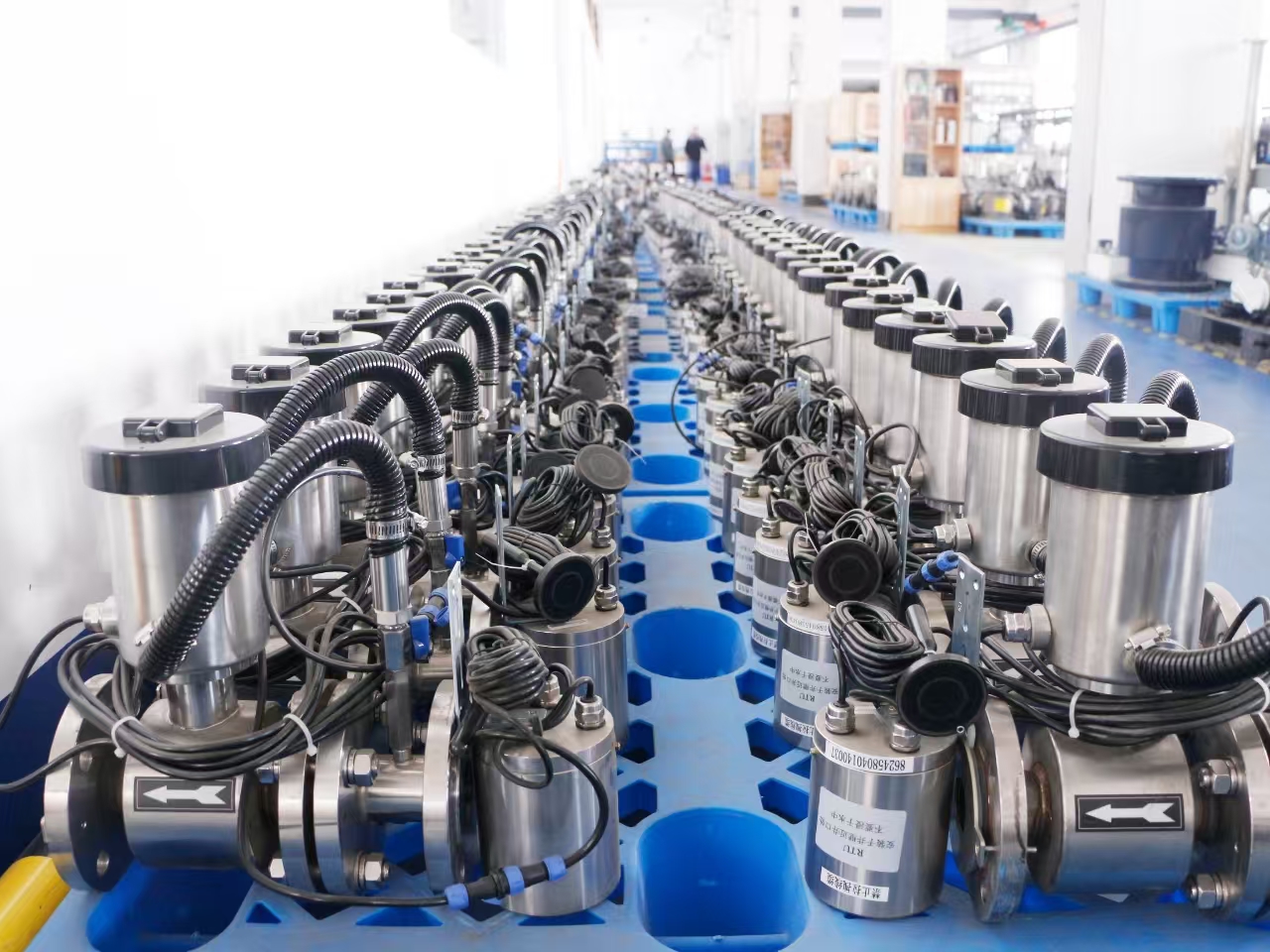
For execution-stage projects, prepare an interface schedule covering the output, protocol, power, hazardous-area classification, pressure rating, wetted material, process connection and acceptance test. The supplied product brochure is available for download.
Have Questions or Need More Details?
Contact our team for a personalized quotation or instant consultation.
Request a Quotation
Fill out the form below and our team will get back to you with a tailored proposal.
WhatsApp Direct Chat
Prefer to chat in real-time? Message us on WhatsApp for instant assistance & quick answers.
- Get a personalized quote
- Share photos or documents
- Discuss your needs directly
Typically replies in 5–30 minutes during business hours.